I happened to find this 3D-printable model of Obi-Wan Kenobi’s lightsaber, so I decided to see if me and my 3D-printer were up to the task. There’s also an article about designing the lightsaber model in the Ultimaker blog.
Printing the pieces took a fair while, and there were several problems with the prints due to bad calibration of my printer. On the bright side, this gave me a good excuse to actually try and get my Solidoodle 2 slightly more correctly adjusted for complex prints.
There are no photos of the early stages of the build, as I was in a bit of a hurry to finish the pieces before I left for a vacation. I did eventually manage to tune my printer well enough to print most of the parts, but the switch and locking pin were way beyond what I can do with my printer. I replaced the locking system with a nyloc nut embedded in the print, and with a hex bolt replacing the pin.
Once printed, I gave the pieces two coats of Smooth-On’s XTC-3D to smoothen out the striations in the prints. Again, in a rush, I applied too much of the stuff, which just added some extra filing and sanding afterwards.
After sanding, I gave all the parts a few coats of paint with an airbrush.
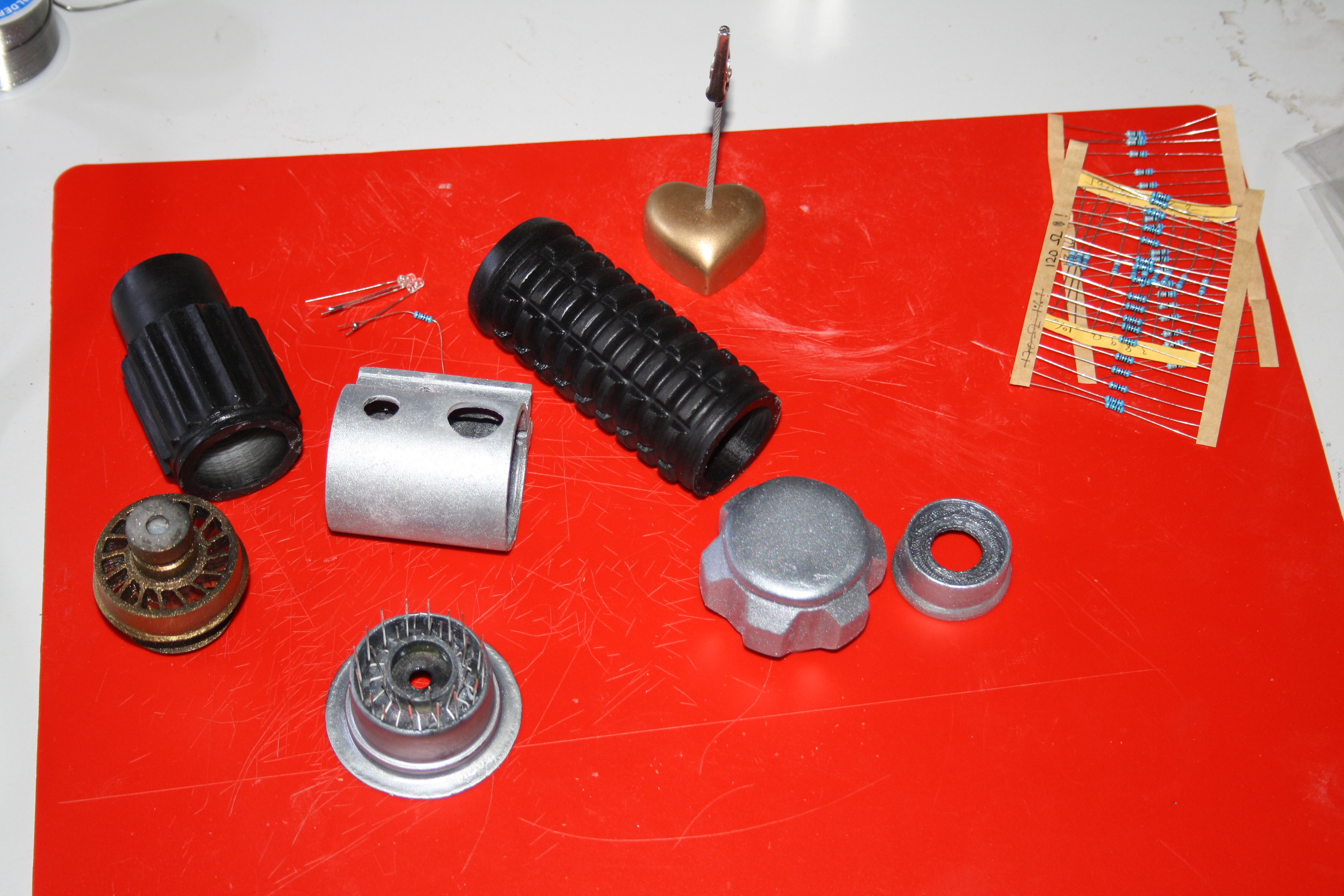
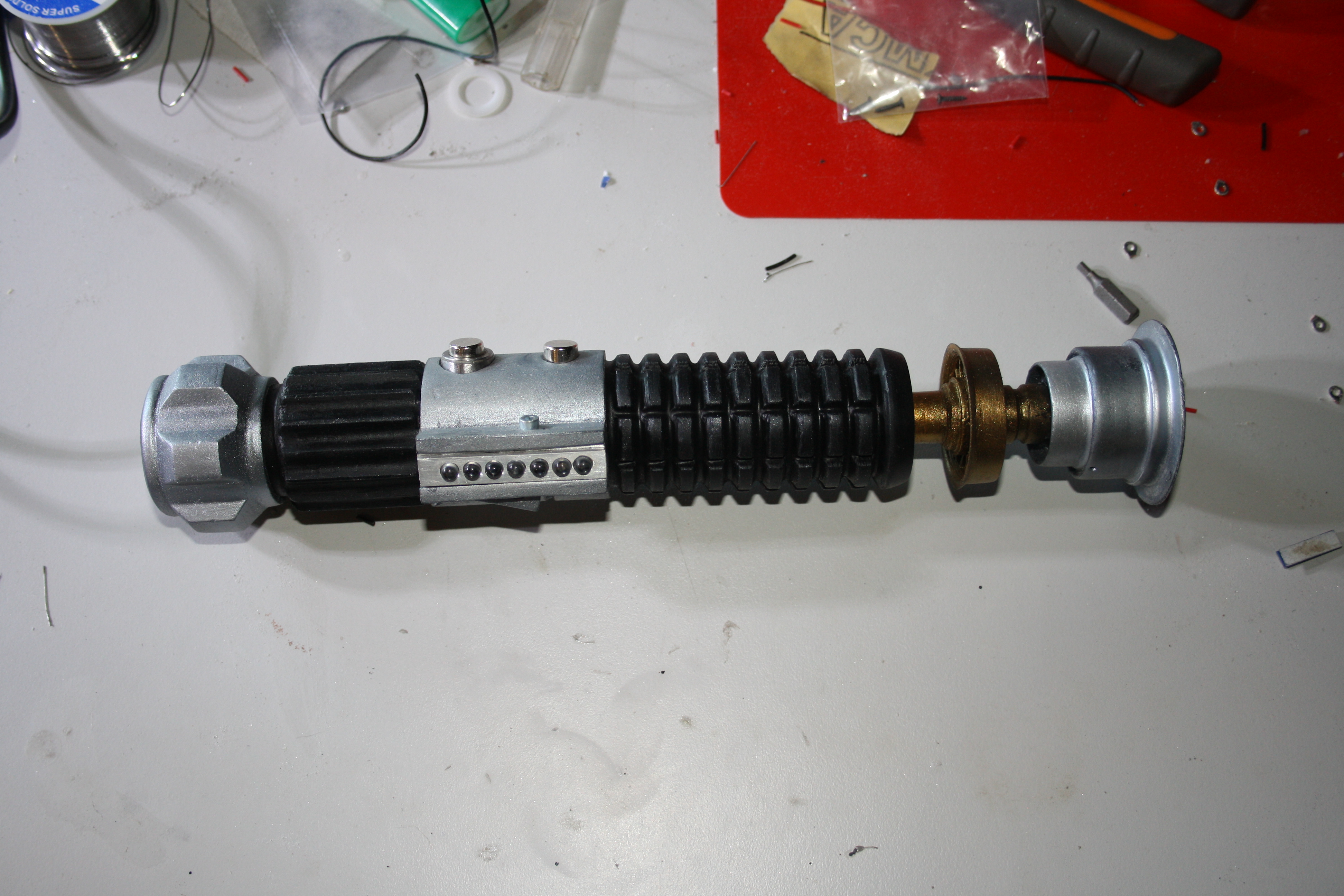
I didn’t feel like making just a static prop, so I came up with the idea of making a flashlight out of it. The holes in the emitter of the lightsaber were enlarged with a drill press to allow fitting of white 3mm LEDs there.
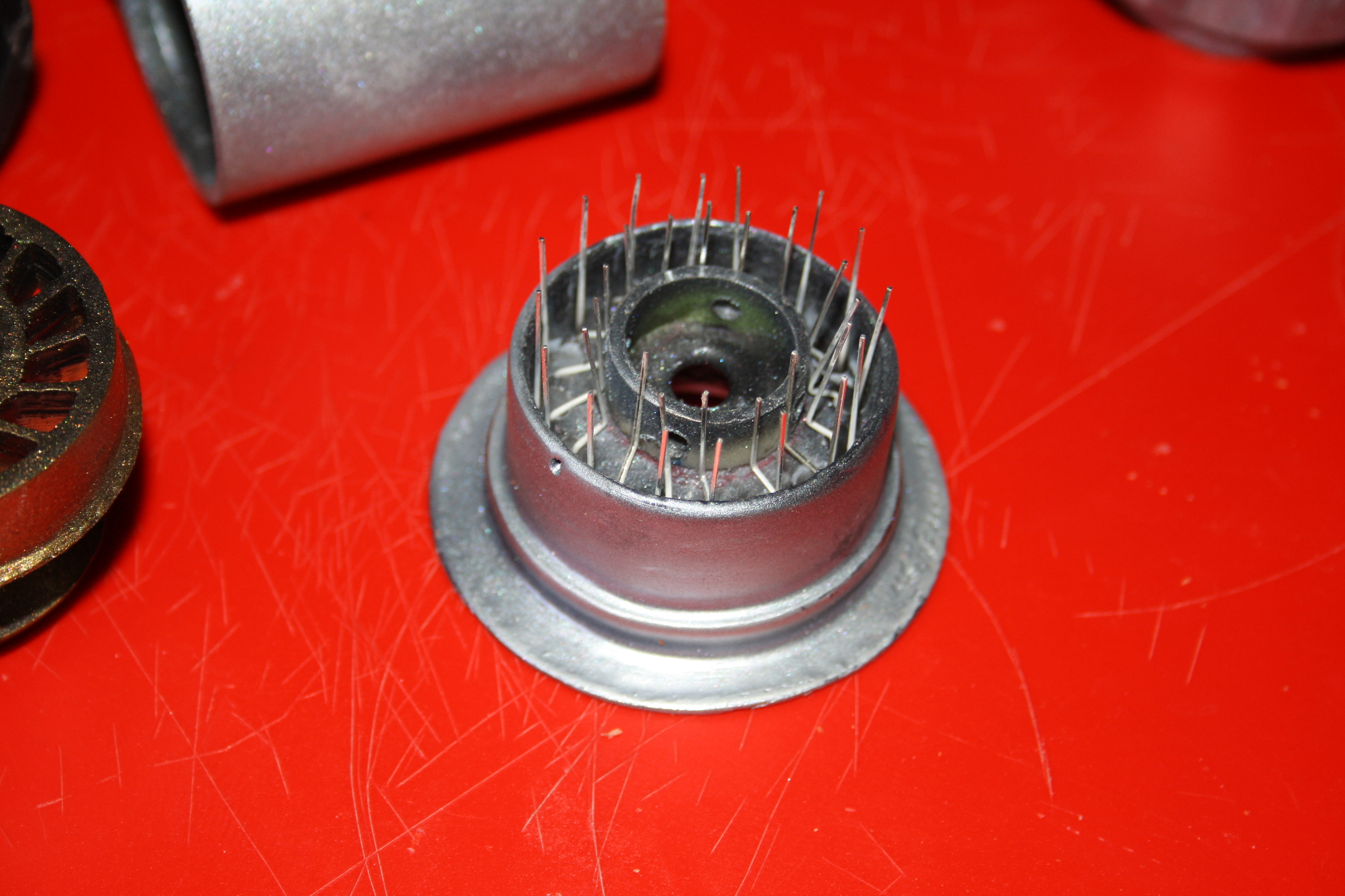


Likewise, the bumps in the “lightbulbs” section were drilled out to accept 5mm LEDs. In the end, I wasn’t happy with the alignment of the holes in the “lightbulbs” part, so I ended up making a new part from aluminium, as I did not have access to my printer at that stage.
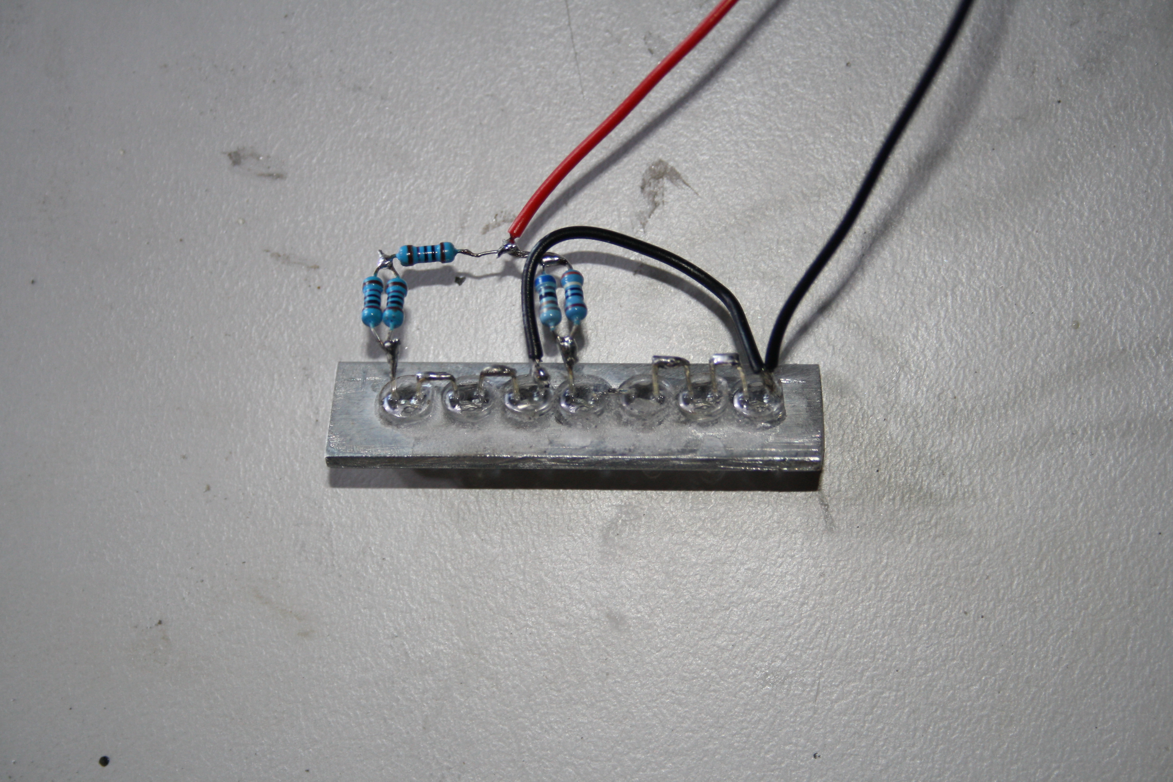
I also discovered that I had lost the “transistors” piece that I had printed. Fortunately, on a trip to a local electronics store I found chromed foot switches that were nearly perfect replacements. This also solved my problem of how to switch the lights on and off. The only thing I had to add was the “collar” around one of the switches. I made one from a piece of metal tubing and a washer.

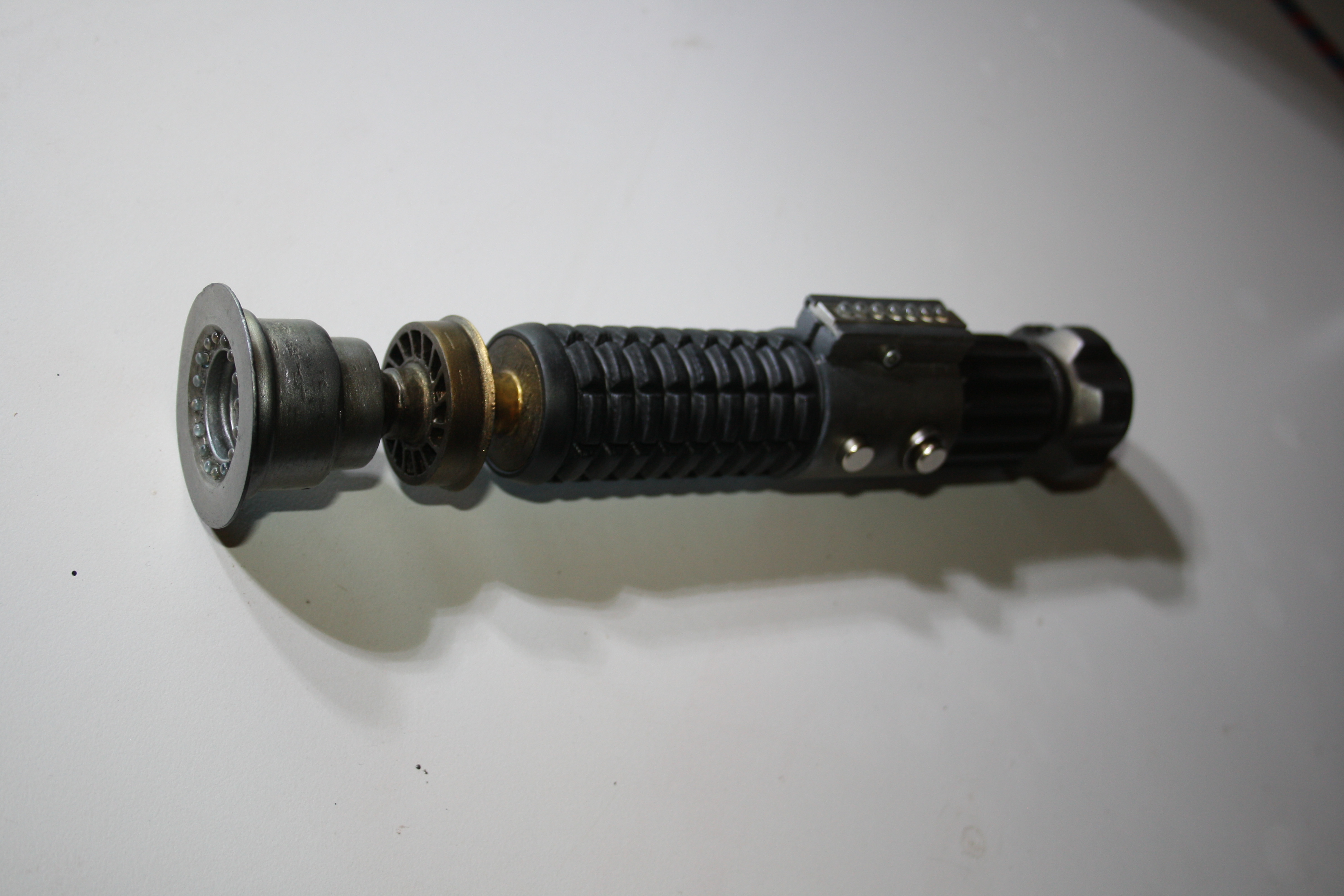
The lights are powered by a 9 volt battery that fits where neatly in the bottom part of the lightsaber handle. After all the lights and switches were wired in, it was time for the first test assembly.
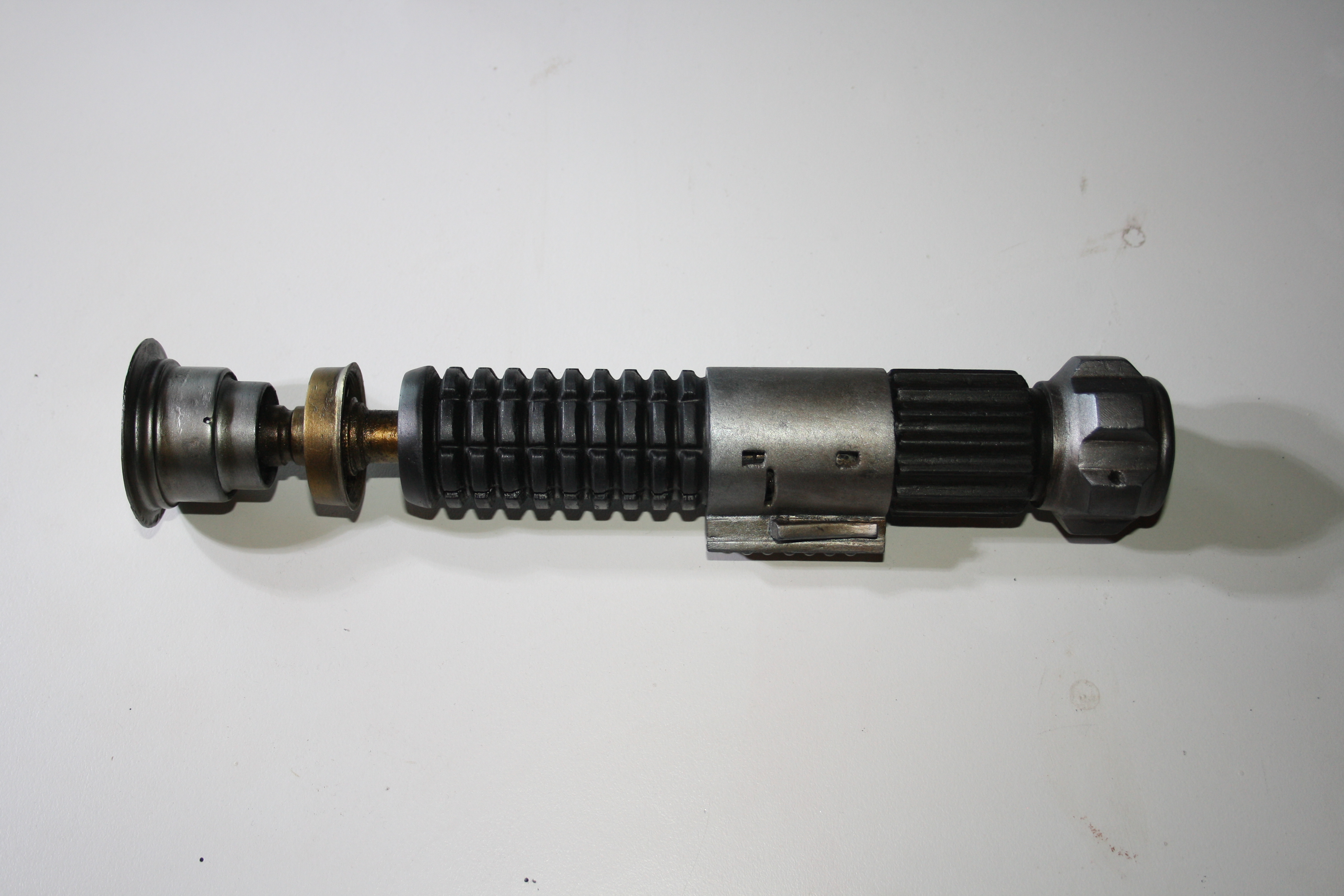
Once assembled, the only thing left was to add a bit of weathering. I did this by airbrushing some transparent blacks on browns on the model and immediately wiping most of the paint off with a rag.